Axminster AWSL Instruction Manual
Browse online or download Instruction Manual for Lathes Axminster AWSL. Axminster AWSL Instruction manual User Manual
- Page / 16
- Table of contents
- BOOKMARKS
Summary of Contents
AWSL WoodturningLatheAxminster Tool Centre,Unit 10 Weycroft Avenue, Axminster, Devon EX13 5PHaxminster.co.ukCode 501245OPTIONAL EXTENSION BED Code 503
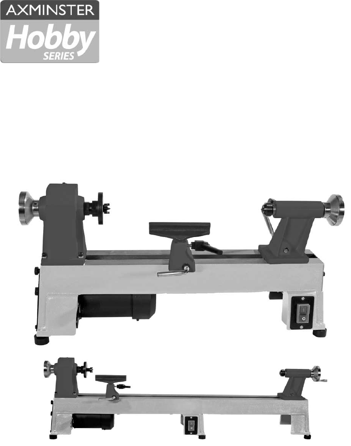
10Parts Description and IdentificationToolrest A stright stem with a shaped cast metal blade forming a ‘T’ profile. It fits into the banjo, and is lo
11Changing the SpeedNote. The lowest speed pulley combination is furthest from the faceplate, i.e. smallestmotor pulley diameter to largest spindle pu
12Parts Breakdown/LIst
13Parts Breakdown/LIst
14Parts Breakdown/LIst
15Notes
Please dispose of packaging for the product in a responsible manner. It is suitable for recycling. Help to protect the environment, take the packaging
Index of ContentsPage No.02Declaration of ConformityIndex of Contents 02 Declaration of Conformity 02What’s in the Box 03General Instruc
03What’s in the BoxGeneral Instructions for 230V MachinesQuantity Item Model NumberBox 1 MC1018 1 No. AWSL Lathe Headstock and T
General Instructions for 230V MachinesSpecific Safety Instructions for Woodturning LathesWork Place/EnvironmentMake sure when the machine is placed th
05Specific Safety Instructions for Woodturning LathesSpecificationInitial Assembly9. Make sure your tools are stored/racked away from the turning area
06Initial AssemblyStep 1Remove the two screws.Step 2Remove the plate andlocate the holes. Step 3Line up the extension bedlocating dowels with the two
07Parts Description and IdentificationBanjo lockLathe bedOn/off SwitchHeadstockHeadstockspindlehandleRevolving CentreFaceplateDrive centreTailstockTai
08Parts Description and IdentificationLathe Bed Cast Iron frame with ground top surfaces and 4 leg extrusions, the leg extrusions have large rect
09Parts Description and IdentificationPivot boltToolrestToolrest lockMotor Access panelTailstockTailstockbarrel lockRevolving centreTailstockhandleTai
Related products and manuals for Lathes Axminster AWSL
 (2 pages)
(28 pages)
(32 pages)
(32 pages)
(24 pages)
(42 pages)
(2 pages)
(28 pages)
(32 pages)
(32 pages)
(24 pages)
(42 pages)
© 2020, manymanuals.com. All rights reserved. | 4.870 s |
 Manymanuals.com
 Manymanuals.de
 Manymanuals.fr
 Manymanuals.it
 Manymanuals.pl
 Manymanuals.cz
 Manymanuals.es
 Manymanuals-pt.com
Comments to this Manuals